


Dubai-based Emirates Trading Agency's (ETA) mechanical and electrical division was the MEP (mechanical, electrical and plumbing) subcontractor for Phase 3 of the Dubai Internet City (DIC) project.
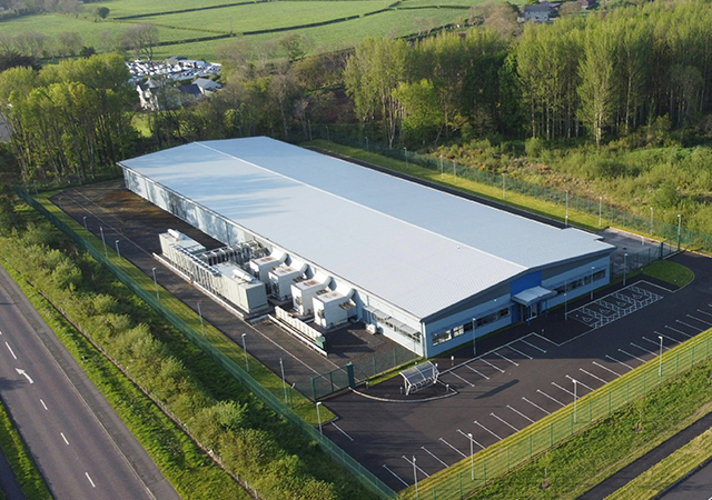
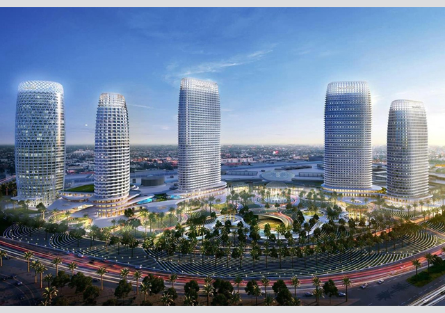
The third phase, part of Dubai Internet City campus, comprises five ground-plus-four-storey buildings namely Compaq, IBM, HP, DIC 1 and DIC 2. A common basement, designed to serve as a car-park and house major mechanical pump rooms, runs beneath the five buildings.
While all the buildings have five leasable floors and a roof to house the mechanical equipment, two of them have an additional upper roof accommodating the chillers.
Electrical
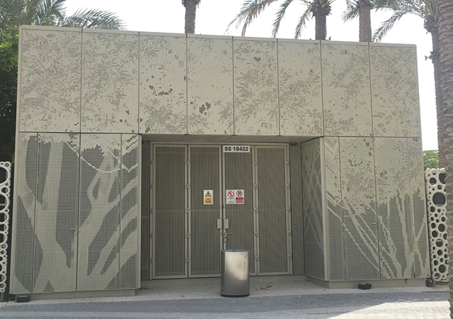
With regards to the electrical distribution, all the buildings all have a substation /LV (low-voltage) room on the ground floor with two of them having an additional sub-station /LV room on the roof to power the chillers.
"The incoming supply to the substation is 11 kV which is stepped down to 380 V and fed to LV panels installed by us," says a spokesman for ETA electromechanical division. Dubai Electricity and Water Authority (Dewa) supplied and installed the 11 kV and 380 V transformers, including associated cabling and termination.
Floor-wise power distribution is via electrical rooms located on every floor. There are also MCCs (motor control centres) in the basement and on the roofs to provide power to mechanical equipment such as AHUs (air handling units), SPFs (staircase pressurization fans) and pumps.
The power supply to the various floors is through an individual feeder to the respective floor SMDBs (sub main distribution boards) located in the electrical rooms.
LV distribution is through dedicated LV rooms of the respective blocks. The LV panel boards involved in the power distribution scheme comprises: Main LV panels and capacitor panels; SMDBs, leasable area and landlord distribution boards, emergency lighting distribution boards and motor control centres.
The spokesman continues: "The electrical services for the entire DIC -Phase III are designed and installed with due consideration to: extreme conditions, internal and external environmental conditions, functional requirements of different areas, personnel safety, reliability of the power supply, simplicity of installation, operation and maintenance, aesthetic and comfort considerations and quality assurance.
"The electrical system and equipment are designed and installed for 380/220 V, 50 Hz in accordance with Dubai Electricity and Water Authority distribution regulations, IEE regulations, British standards and code of practice.
"All mechanical equipment such as pumps, supply fans, return fans, heaters and staircase pressurisation fans installed in this project are fed through appropriately-located motor control centres. Necessary starters, variable frequency drives, contactors and protective devices are housed in these panels based on the project specifications and characteristics of connected equipment and in line with Dewa requirements.
"There is also a separate interfacing section housing transformers, relays, fuses, terminal blocks to interface with other systems such as building management system (BMS) and fire alarm.
"A total of five generators have been installed in this project, one per building, ranging from 200 KVA to 300 KVA. All gensets provided are of higher ratings and suitably de-rated considering the site conditions, in line with project specifications and client requirements.
"The main connected load onto the gensets is the UPS (uninterruptible power supply) and the staircase pressurisation fans on the roof.
The light fixtures have been carefully selected to suit the area of usage and applications."
The wiring accessories are of different carefully-selected finishes. In general, three types of finishes have been used: white plastic for all front-of-house and back-of-house areas, metal clad for all plant rooms and weatherproof for external areas.
There are also emergency stop locks located adjacent to every mechanical equipment in order to shut down the associated equipment in case of emergency and routine maintenance situations.
A wide range of containment has been used including cable ladders, cable trays, GI trunking, flush floor trunking and accessories, skirting trunking and accessories, cable baskets and accessories.
The integrated fire alarm/voice alarm and fire telephone system installed in this project is the EST3 - Signature series, an intelligent microprocessor-based system from Edwards-Canada, one of the most modern and sophisticated equipment available on the market. It comprises devices such as smoke detectors, manual call points, strobe lights, speakers and fire telephone in order to detect fire, broadcast fire messages and establish communication in the event of a fire. Also, appropriate interface units have been provided to control and monitor the operations associated with fire and life safety.
Every building is equipped with a fire alarm control panel with loops to service all floors. In addition, the panels of all five buildings are interlinked with the main fire alarm panel to have a global networking and communications facility. There is also a dedicated PC in the main control room to display the graphics/text messages during fire conditions. Each fire alarm panel is integrated with the BMS.
The emergency lighting system is centralised with an inverter back-up to provide power for up to three hours in the event of a mains failure.
An ABB - I-Bus EIB low voltage intelligent lighting control system has been installed for the project comprising lighting control module (LCMs) in each lighting control panel on each floor and movement sensors installed in all toilet areas. The complete lighting control system is interfaced with the BMS system.
Security system
Security is ensured by a combined CCTV and an online access control system for main entry and exit points - main entrance, car park barriers, basement staircase entries; control rooms and electrical/plant rooms. The peripherals forming part of online access control system are door contacts, electro magnet, electric locks, car readers and request to exit button. These systems are interfaced with the CCTV and fire alarm system. It is also integrated with the BMS system through the LON (LAN) network.
The CCTV system comprises 81 cameras of different types to monitor entry and exit points to the buildings and also secured areas such as MDF and plant rooms.
One UPS system rated at 30KVA with an autonomy of 30 minutes is provided for each building to back-up critical loads such as the MDF room patch panels and hubs for IT network.
HVAC system
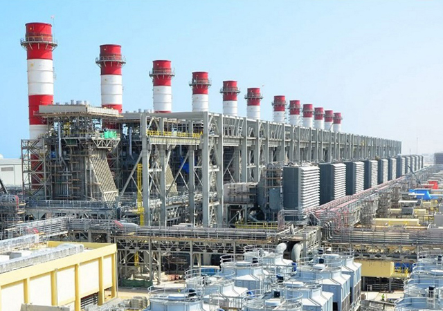
MEP works consist of the central air-conditioning plant with air-cooled chillers, chilled water pumps, AHUs and FCUs (fan coil units) linked to the BMS. Each chiller has an installed capacity of 304 TR.
There are 10 chillers located on the roof of the DIC 1 and HP buildings. All air-handling units are located on the second roof level of DIC 1 and HP buildings near the chillers. The secondary pumps are located in the basement, second floor and the roof.
There are 12 primary pumps, six on the HP roof 2 and six on the DIC 1 building's second roof level. The primary pumps feed the chillers and up to the suction of the secondary pumps.
There are eight AHUs (air handling units) for each building, six of which are with variable speed drive, one is constant speed drive and one fresh air AHU. AHUs with variable speed drive feed all the leasable areas through variable air volume units (VAV) boxes, which are of the pressure independent type and are controlled to maintain the required air volume and temperature. Each AHU has a return air fan connected to the return path of the air side circuit with a variable speed drive.
The fresh air AHU feeds the treated fresh air to each AHU and has a heat recovery unit. The extract air from the toilet is exhausted to the atmosphere through the heat recovery wheel exchanging heat with the fresh air and thus reducing the load on the fresh air AHU coil.
The following design parameters are required to be maintained during summer: External thermal design conditions - 115 degree F dry bulb 84 deg F wet bulb; internal - 72 deg F dry bulb, relative humidity 40 to 50 per cent.
Plumbing & fire fighting system
Water supply from Dewa is fed to three RCC water tanks: a domestic water tank, a fire water tank and an irrigation water tank located under the entrance and exit ramp with pump rooms located adjacent to them. Each tank is connected to the Dewa main through a series of two water meters - landlord water meter and Dewa water meter.
The Domestic water tank and pump room is located in the basement between the HP and IBM blocks. Water is supplied to all five buildings by means of a discharge header (6" upvc pipe) which is branched into two sub headers.
"Since the pressure required in the buildings has to be constant and also since all the buildings are located at a distance from each other, it is essential to provides a higher pressure in the header than the requirement.
"In order to achieve a constant pressure (lower than header pressure) a pressure reducing valve (PRV) package with a bypass arrangement is installed in branches to individual buildings risers.
"The outlet pressure in PRVs is set to obtain satisfactory working pressure at the highest point in the building. The riser to each building is a 4" upvc drainpipe with branch-off in every floor. One sub-riser is fed to the refuse rooms located in every floor from this main riser," the spokesman says.
A water hammer arrestor is provided in every toilet to reduce water hammer effect as the system is pressurized.
Hot water supply - cold water is fed to an electric water heater (100 litres capacity) located above in the shower area in every toilet and electric water heater (50-litre capacity) above the pantry areas. Hot water is supplied by copper piping.
The whole section of this pipe is insulated with closed cell elastomeric foam insulation and section of this pipe in the basement is aluminium cladded for extra protection.
After chlorination and thorough flushing the domestic water supply is continuously ozonised by means of an ozone generator located inside the domestic water pump room. The ozone is injected into the domestic water tank as and when required.


