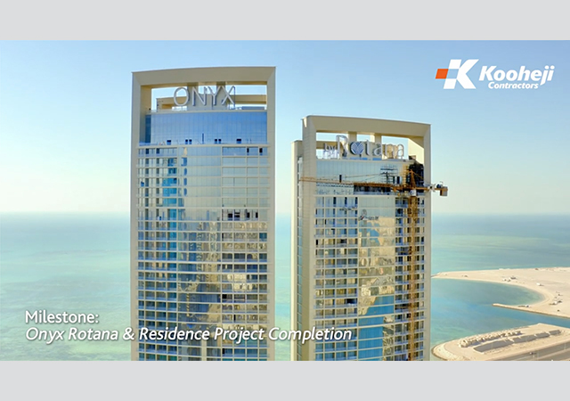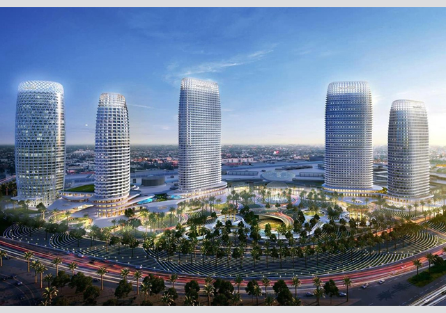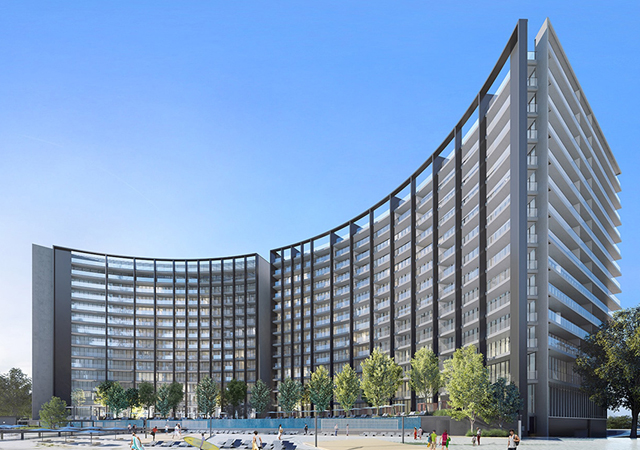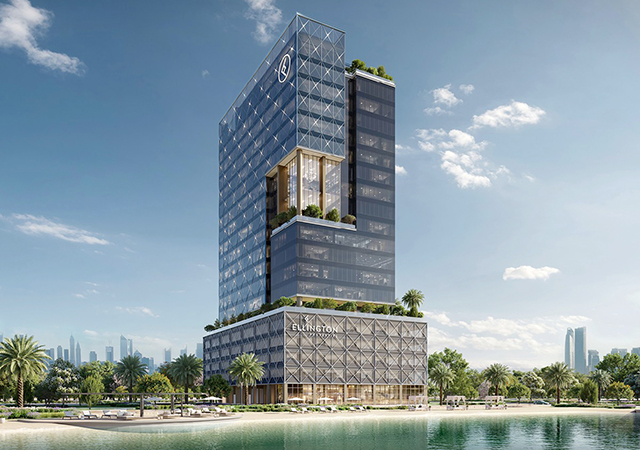
Visually, it is often the goal of skyscraper architecture to define an individual character through the design of any skyscraper’s façade.
This face or skin, wrapped to the structural frame beneath, is often key to an architect's desire to evoke our emotions, instilling a sense of grandeur as if each new skyscraper were an artist's sculpture.
In recent decades, the desire for taller structures and, particularly, those that are competing for recognition to be among the tallest, if not the world’s tallest, is reason to review the fire safety issues related to façade or curtain wall design. Additionally, due to the creativity of architects, new and unique façade designs are continually appearing. These unique designs veer from the more traditional continuous vertical façade surfaces of the past, often using curved surfaces and rotated floor plates that complicate the façade connections and hidden details of fire barrier assemblies. Double curtain wall systems, where two glazed walls are separated by distances of less than a meter are being implemented. These twisted façade designs, double skin designs and other new facade creations pose new challenges from a fire engineering perspective.
The risk of fire spread through articulated elements of the façade or vertically around the facade via the mechanism of flame leap, poses new concerns for the newest class of super high-rise structures.
The concerns revolve around the issues of fire department response capabilities, reliability of sprinkler systems and associated water supplies, and the characteristics of the building and building's occupants. More importantly, as architects develop new and leading edge creative curtain wall designs, it becomes more critical to consider the risk factors that can impact the building's overall level of fire safety.
Mechanisms of fire spread
Our understanding of the mechanisms of floor-to-floor fire spread at the curtain-wall have been established by the work of fire researchers and fire engineers dating back to the 1960s and 70s, curtain-wall fire testing work done in the1990s and the continuing testing efforts of product manufacturers and testing laboratories.
From a fire dynamics perspective, we know that flames emitting from an exterior window can extend higher than 5 m (16.5 ft) above the top of the window. Yokoi reported such results in 1960. One test of Yokoi's was a test room with plywood walls/ceilings and a fire load of 40 kg/sq m (8 lb/ft2), which is characteristic of residential occupancies and at the lower end of the fire load scale.
The hot gases from the fire room window measured 400 to 600 deg C at 1,750 mm above the top edge of the fire room window. The glass broke out under this exposure.
Analysis of 400 fire compartment experiments (Thomas and Heselden 1972) helped to more fully explain the physical phenomena of ventilation-controlled fires, representing the scenario where a fire burning in a building breaks the window glazing, permitting hot gases to flow out the top portion of the opening. A portion of the hot gases are unable to burn inside the room due to limited air (ventilation controlled) but, upon movement to the exterior, encounter sufficient air entrainment, allowing the hot fuel gases to burn outside the building. The result is a flame projecting out and upward from the window. From a visual perspective, flame extension is estimated at the point that flame temperature drops below 540 deg C, which corresponds to the flame no longer appearing luminous.
Taking the data of various researchers, Ove Arup & Partners was commissioned to develop a number of correlations to estimate flame projections and flame temperatures under natural or forced draft conditions (Law and O'Brien 1975). We know from this work that the fire flame projection and temperature profile will be a factor of window area and height, room geometry, fuel contents and burning rate, and wind velocity. In review, our knowledge of fire dynamics allows us to understand how the building interior areas and curtain wall can be attacked by fire in three principal ways. Figure 1 illustrates the potential temperature and heat flux characteristics of a fully developed, unsprinklered compartment fire.
The three principal mechanisms at work in Figure 1 are as follows:
• Inside – flames and fire gases in the building attack the interior surfaces and details of the curtain wall and associated perimeter fire barrier materials;
• Outside – flames and hot gases projecting from fire-broken glazing or other openings directly impinge on the curtain wall exterior face (convection);
• Outside – flames projecting from fire-broken glazing or other openings radiate heat to and through glazed surfaces or through other openings to building contents and furnishings.
The building’s exterior architectural features incorporated as elements of the façade or, which perhaps, are due to the structural floor plate changes, can impact the flame projection and associated corrective and radiation heat exposure to the façade. Work done at the National Research Council of Canada (Oleszkiewicz 1990-91), showed the extent to which horizontal projection above flames issuing from a window below can be effective at reducing the flame exposure. This work also showed that vertical exterior elements could have a negative impact by increasing the vertical projection of flames along a façade. Figure 2 illustrates the change in fire flame position and extension due to a horizontal projection above a window and vertical panels located at each side of a window.
In terms of hazard reduction or increase, Figure 3 illustrates how the deflection of the flame by a horizontal projection reduces the heat transferred to the wall above the burning compartment. Conversely, the vertical projections increase the heat transfer to the wall. The increase in heat flux with vertical projections installed is due to the restriction of lateral air entrainment, which forces a lengthening of the gas plume as it seeks to entrain more air for combustion.
Current code practices
Today's codes such as the 2007 International Building Code and the National Fire Protection Association's 2006 Building Construction and Safety Code (NFPA 5000) recognise that with a properly designed and operational sprinkler system, the threat of fire spread along the exterior of the curtain wall is effectively mitigated. This is a critical assumption that deserves further consideration in the context of super high-rise buildings and is discussed in detail later.
From a fire containment perspective, there are currently two basic ways to provide a code complying curtain-wall design in fully-sprinklered buildings. The most basic approach is for the curtain wall to be supported directly on the structural floor slab edge, which precludes any gap or joint condition, given that the floor slab is continuous to or extends past the building envelope. This type of installation would permit floor-to-floor glazed curtain-wall assemblies in fully sprinklered buildings as shown in Figure 4.
This approach is sometimes observed in high-rise building design, but it is not the most common approach for the installation and support of curtain walls. The second approach is applicable when the curtain-wall assembly is positioned just outside the edge of a fire-rated floor system, such that a void space results between the floor system and the curtain-wall assembly as shown in Figure 5.
The noted codes require that the void space at the slab edge in Figure 5 be sealed with an approved material or system to prevent the interior spread of fire (IBC 713.4, NFPA 5000 8.9.3). This requires some form of a joint system or what today are called 'perimeter fire barrier systems.” The basic performance criterion for these perimeter fire barrier systems is one of the following:
• Such material or systems shall be securely installed and capable of preventing the passage of flame and hot gases sufficient to ignite cotton waste where subject to ASTM E119 time-temperature fire conditions for a time period equal to the fire resistance of the floor assembly; or
• Such material or systems are to be tested in accordance with ASTM E2307, 'Standard Test Method for Determining Fire Resistance of Perimeter Fire Barrier Systems Using Intermediate-Scale Multi-Storey Test Apparatus'.
The methodology for compliance with either of these criteria is essentially the same, the former being the original performance intent statement which evolved into the more recent and formally defined ASTM standard. Although a defined ASTM standard does exist, there is confusion in the building industry among design architects and fire engineers resulting from differences in the rating criteria imposed by various testing laboratories.
Underwriters Laboratories (UL) certifies perimeter fire barrier systems under the product category 'Perimeter Fire Barrier Containment Systems'. The systems certified by UL use the same two-storey large-scale fire test apparatus as are described in the ASTM E2307 standard. However, the systems certified by UL are measured in four aspects – an F-Rating, a T-Rating, an Integrity Rating and an Insulation Rating. The ASTM E2307 standard requires the reporting of an F-Rating and a T-Rating. This is in contrast to the F-rating, which is the only requirement stipulated by the 2006 IBC and NFPA 5000 (per code change proposal).
It is important to understand these ratings and the purpose behind each rating:
F-Rating: This evaluates the most fundamental function of a perimeter fire barrier system. The F-rating is given if the vertical passage of flame and hot gases sufficient to ignite a cotton pad is prevented by the perimeter fire barrier system. This is testing the ability of the perimeter fire barrier system to maintain fire resistance in the void space between the interior surface of the curtain-wall assembly and the floor slab edge. The F-rating is expressed in hours (for example. two hours) for comparison to the fire resistance rating of an associated floor assembly.
T-Rating: This evaluates the extent of temperature increase on the non-fire side of the perimeter fire barrier system. The temperature measurements are taken at a point 25.4 mm or less above the fill materials perimeter fire barrier system. A T-rating is expressed in hours for perimeter fire barrier systems that do not show a temperature rise of 181 deg C for any individual thermocouple, or a temperature rise of 139 deg C for averaged thermocouple points (required for wide voids). T-ratings are typically in on the order of 0, 1/4 and 1/2 hour.
Insulation rating: This rating provided under the UL certification process is similar to the T-Rating per the ASTM E2307 procedure; however, UL additionally evaluates the temperature rise on the unexposed interior surface of the curtain-wall assembly above the fill materials. This is intended to determine if fire can spread to a floor above through the curtain-wall construction and not just the fill material of the perimeter fire barrier system. Insulation ratings are typically in on the order of 0, ¼ and ½ hour.
Integrity rating: This rating provided under the UL certification process is similar to the F-Rating per the ASTM E2307 procedure; however, UL additionally evaluates if there is any flame passage or surface flaming on the interior surface of the curtain-wall assembly above the fill materials. In addition, the glazing above the fire-exposed floor is monitored to determine when the glazing breaks. The intent of monitoring the glazing integrity is to identify how long in hours the curtain-wall glazing will survive, resisting the fire leapfrog that has been observed to occur in multi-storey buildings.
The F-Rating and Integrity Rating are sometimes interrelated in that a perimeter fire barrier system will not be capable of achieving an F-Rating if the curtain-wall does not maintain integrity and allows the perimeter fire barrier system to become dislocated or displaced during the fire test. This is, generally, the case for fully-glazed curtainwall systems that incorporate glazed insulated spandrel panels. The failure mode for such assemblies occurs if the spandrel glazing and framing members are not sufficiently insulated. Under these conditions, the perimeter fire barrier system fill materials will fall out of place when the glazing panel and associated insulation fail to maintain a compression fit with the fill materials of the perimeter fire barrier system. This has often resulted in confusion and frustration for architects desiring to use full-height, floor-to-floor glazed openings.
Given that the 2006 IBC and NFPA 5000 codes only require the void at the intersection of the curtain-wall and the floor assembly be protected with fire barrier fill materials, there is often confusion. There are no formally published tested perimeter fire barrier systems that allow for floor-to floor height vision glazing. This is mostly an artifact of the nature of compression fit type fire barrier methods and their integration with fully-glazed curtain walls. If a tested perimeter fire barrier system could be shown to stay in place in the void after the glazing failed, then code compliance would be achieved. Yet, the extent of the failed glazing may raise concerns for flames readily entering adjacent spaces above.
This lack of such capable perimeter fire barrier systems poses a challenge to curtain-wall designers/architects who wish to create façades using expansive vision glass panels. The issue of performance expectations of non-fire-rated curtain-walls and the associated perimeter fire barrier assembly has been a significant item of discussion in the US. As a result of recent code changes, it is reported (Koffel 2005) that the code intent is to recognise that if the curtain-wall assembly does not have the same fire-resistive capability of the floor slab, then the system protecting the void space need not perform after curtain-wall integrity is lost.
Loss history
The threat of floor-to-floor fire spread at the exterior façade of any building is real and confirmed via actual unsprinklered high-rise building fires around the world. Several observations are apparent upon review of seven of these incidents and which point to fire risk assessment considerations. Some of these are as follows:
• Large fire department manpower and apparatus response was observed in six of the seven incidents. In two cases, the fire departments abandoned their efforts due to fears of structural collapse;
• In several incidents, occupants fled to the roof of the building to be rescued by helicopters. In contrast, many of today's super high-rise buildings will not have an accessible roof to facilitate occupant rescue operations.
• Fire spread was attributable to broken windows and flame extension along the exterior facades. The number of floors involved was three of 100 storeys, 28 of 31 storeys, two of 32 storeys, 23 of 30 storeys, four of 62 storeys, eight of 30 storeys, and 23 of 56 storeys, respectively, for the seven incidents;
• The value of sprinklers was observed in the one major incident where 10 sprinklers supplied by fire department pumpers are reported to have stopped fire spread. It is reported (Klem 1991) that the sprinklers activated as a result of heat transmission via broken windows and through the void space that existed between the floor slab and exterior granite façade, as well as, heat conduction through the floor slab. As combustibles ignited at multiple locations the sprinklers operated and extinguished the fires.
Curtain wall components
Curtain walls are a relatively complex combination of components that include aluminium frames, vision glass; spandrel panels of glass, metal or stone; metal back pans; insulation; gaskets; sealants; and anchors or connectors of steel or aluminium. Given a fully-developed fire exposure in a room or space (that is, the sprinkler system out of service or failure scenario) bordered by a building's curtain-wall system, it can be expected that vision glass failure will occur within minutes. Once the failure occurs and flames are extending to the exterior, the various curtain-wall components and any perimeter fire barrier system are then subject to thermal forces and degradation that can result in fire spread to the floor above. The nature of the curtain-wall design will dictate the relative capability to resist floor-to-floor fire spread.
Key factors that impact the curtain wall’s resistance to vertical fire spread are:
• Full height or partial height (that is, spandrel panel design) vision glass systems;
• Nature of the glass used to construct the glazing system;
• Nature of the curtain-wall components (such as framing, spandrel panels);
• Height of spandrel panels;
• Vertical or horizontal projections on exterior that may deflect or enhance flame behaviour;
• Building geometry at curtain-wall – twister, staggered, sloped, among others;
• Operable windows/openings – size, vertical or horizontal orientation; and
• Ability of perimeter fire barrier system to remain in void during fire exposure.
When full-height vision glass systems are used, flame extension and heat fluxes to the window areas above can be expected to be greater than that expected for curtain-walls using a spandrel panel design. A spandrel panel design will limit the flame extension and reduce heat flux to the areas above by providing an opaque surface to block the heat transfer. To prevent the leapfrog effect using a spandrel design requires a vertical spandrel dimension of approximately 4 and 5 ft in order to match the performance, respectively, of one and two hour fire-rated floors (Shriver 2006).
The construction of the spandrel can be an important factor to the performance of the perimeter fire barrier system. Typical aluminium-framed curtain-walls using spandrel glass require that the glass be appropriately insulated using mineral wool rather than fibreglass-based insulations that will melt. Additionally, the aluminium mullions require insulation protection; otherwise the aluminium frame will melt and no longer support the wall system. These measures will help keep the glass spandrel panel and any associated fire barrier system intact.
Precast panels offer the advantage of high resistance to heat exposure and offer a solid rigid surface for securely positioning or compression fitting a perimeter fire barrier system into the void between the precast panel and the floor slab edge. Metal curtain-wall panels or metal back pans that, when subjected to the fire heat, may warp or distort allowing gaps to develop at the perimeter fire barrier system, need specific measures to stiffen the metal pans.
Glass used in curtain-wall assemblies may be one of several types – float glass which may be heat strengthened or tempered glass, and laminated or wired glass. Vision glass can be single, double or triple-glazed, and are typically assembled into an insulating glass unit (IGU). Vision glass may also be tinted to provide a heat-absorbing quality or coated to provide a heat reflective capability. All of these features can impact the performance of glass under fire exposure, However, very little is currently known about the fire performance of the wide variety of IGUs that are possible. What we do know about glass performance is limited to standard single-glazed assemblies and, recently, some information on double glazed units has been presented.
Small-scale tests (Kim, Lougheed 1990) have shown that plain float glass exposed to radiation at 10 kW/sq m and 40 kW/sq m in glass broke at temperatures of 150 to 175 deg C within eight minutes and one minute, respectively. In these same tests, heat-strengthened and tempered glass survived 43 kW/sq m for 20 minutes without breaking while reaching temperatures of 350 deg C. Additional small-scale tests (Mowrer 1998) showed that single-glazed windows failed in the range of 40 to 50 kW/sq m, noting that 33 kW/sq m appeared to be a level below which failure did not occur.
Of course, the ignition of materials on the unexposed side of a window is of key importance. It is essential to know what quantity of radiation will be transmitted through a glass layer to combustible materials on the unexposed side, given that 10 to 40 kW/sq m can ignite materials in the range of lightweight fabric materials to common cellulosics (Deal 1995). Again, the results of small-scale tests have shown that a double-glazed assembly will absorb approximately 90 per cent of the thermal flux and is capable of reducing heat flux from 100 kW/sq m to 8 kW/sq m (unsprinklered conditions). This is significant only if the glass does not break and maintains its integrity as a solid barrier. A recent study (Shields, Silcock, Flood 2005) indicates that double-glazed systems exposed to heat fluxes as high as 25 to 170 kW/sq m provided much better integrity than single-glazed systems.
Tests using more fire-resistant glass products (Manzello, et al 2007), known as SAFTI Superlite II XL and Superlite I, showed that single-pane glass would fall out of the frame at temperatures of 400 to 500 deg C with nearby heat fluxes measured at 50 to 70 kW/sq m.
This brief summary of available data suggests some limits of performance for glass breakage, fallout and reduction of heat flux to combustible materials. However, more testing to determine the performance of large IGUs is needed to better understand these fire-related performance metrics. It may be that actual IGUs may show fire performance benefits not yet understood, however, full installations with framing elements, sealants and gaskets may play a key role – positive or negative. Such full-scale installations are not known to have been tested to any degree that allows for reasonable conclusions about installed performance.
Building geometry and exterior projections of the curtain-wall or building structural elements can have a beneficial or negative effect on flame length extension and heat flux exposure to curtain-wall elements above the fire compartment. This can be particularly important if operable windows or ventilation openings are used. Any such opening can allow the unrestricted passage of flames and hot gases from a fire on a floor below into that above. The position of the window or ventilation opening relative to the expected flame extension is important in assessment of the leapfrog risk.
Risk assessment factors
Several factors to consider in a risk assessment of leapfrog fire spread at the building façade include, but may not be limited to, the following:
• Automatic sprinkler systems' reliability;
• Fire department/brigade response capabilities;
• Building height;
• Building occupancy considerations – for example, office, residential, hospitals, mercantile;
• Building compartmentation features;
• Building evacuation strategies;
• Fire hazard – fuel loads, continuity of combustibles, compartment sizes; and
• Security threat assessment scenarios.
Sprinklered high-rise buildings have a very successful record of life safety and property protection performance. For this reason, the IBC and NFPA 5000 do not require fire resistance-rated spandrels or flame deflectors at the building façade in fully-sprinklered buildings. Reliance on sprinkler systems becomes exceedingly more critical for super high-rises. As the height of buildings increase, so does the complexity of sprinkler systems with an integrated network of piping zones, valves, pumps, power supplies, and water supply tanks. Many components are required to be operational and operated properly for the sprinkler system’s success.
Sprinkler system maintenance can be a major maintenance activity for today’s super high-rise buildings and is key to successful performance. A recent analysis (Hall 2006) of data from the National Fire Incident Reporting System (US data) indicates that for all building types, sprinklers failed to operate in seven per cent of structure fires. The identified reasons for these failures were 65 per cent of the systems were shut off, 16 per cent were defeated by manual intervention, 11 per cent were due to lack of maintenance, five per cent of the systems were the wrong type, and three per cent were due to damaged system components. These failure rates may or may not be applicable to new super high-rise buildings, but it is important to note that human error is the primary factor. Consequently, it is important for buildings with complex sprinkler system design to have features and redundancies that can overt issues of human error and maximize sprinkler system reliability.
Sprinkler system designs can be enhanced to improve the reliability. Gravity feed systems that do not rely solely on electric pumps and emergency power supplies can assure that natural pressures are available to supply sprinklers. Also, piping schemes that use riser cross-connections or feeds from alternate floors can provide additional assurances that a single closed valve does not negate sprinkler water flow. Electrical supervision of valves and other sprinkler components has long been recognised to be a most important feature to monitor sprinkler operational status.
If buildings' sprinkler systems can be designed so that successive floors cannot be turned off with a single valve, then a significant level of redundancy to protect against leapfrog can be maintained.
Fire department response capabilities need to factor into the leapfrog analysis for super high-rise buildings. Prior incidents in unsprinklered buildings demonstrate the difficulty that large, capable fire departments may have for buildings 60 storeys or less in height. Consider that many of the new class of high-rise buildings will double or triple this height. If the local fire department does not have the response capabilities and response plan to handle an unsprinklered fire in a super high-rise building, then, again, great reliance is shifted to the automatic sprinkler system.
Several basic building features and occupancy considerations that may impact the assessment of leapfrog risk are:
• Assembly occupancies – have large and potentially dense population of occupants. Often these occupancies are found at the very top levels of super high-rise buildings.
• High-rise residential – The defend-in-place concept has been used in apartment buildings of fire-resistive construction, where it can be safer to remain in the apartment than to attempt evacuation. If the defend-in-place concept is to be viable for the wide variety of possible fire scenarios, then the leapfrog issue needs to be addressed. Human behaviour has been, on several occasions, cited as playing a major role in the fatalities and injuries in high-rise residential buildings (Macdonald 1985, Proulx 1996). Frequently, occupants who stayed in their apartments or hotel rooms were safe and uninjured, while those who evacuated became casualties. In an unsprinklered super high-rise fire scenario, maintaining safe floor areas (safe from leapfrog effect) for residential occupancies could be a critical need.
• Hospital facilities – This may be the most critical situation that deserves consideration of the leapfrog risk. Horizontal exits, where a floor is subdivided into two fire areas, are often used in hospital facilities and can be a mitigating factor in the risk assessment for hospitals or other occupancy groups.
• Super-tall buildings – buildings with large occupant loads and long total evacuation times. In an unsprinklered super high-rise fire scenario, fire spread by vertical means, whether exterior or interior, may unnecessarily subject large numbers of occupants to adverse conditions from a single fire event. The relative fire hazard of various occupancies can present varying levels of concern in assessment of leapfrog risk. Residential occupancies are generally well-compartmented units. In the event of a sprinkler failure and fire spread to a residential unit on the floor above, it should be recognised that the fire would not propagate readily due to the fire-resistive enclosure walls of apartment units. Note that this generally assumes vertical stacking of units. Conversely, in a retail or office occupancy, there is far less subdivision to provide passive fire containment, increasing the risk of fire spread.
Security threat assessment scenarios should consider the impact of any damage scenarios on the performance of the buildings fire protection features and, specifically the sprinkler systems. The survivability of sprinkler system features and water supplies may be critical to prevent a major fire spread event that results from a security threat scenario.
Conclusion
The risks of fire spread related to super high-rise buildings and the facades that define their character has not been well examined. Current code practices recognise the successful record of fully sprinkler-protected high-rise buildings and only require that the void space between the curtain-wall and the floor slab be resistive to fire spread using a perimeter fire barrier system. These curtain-wall code allowances are key to providing architects with the design freedom to design unique and creative facades. However, the rating systems used by testing laboratories has created confusion about what type of a perimeter fire barrier system and associated curtain wall system is appropriate.
The rating systems focus narrowly (yet appropriately) on the fire testing of specific assemblies that are not necessarily consistent with the goals of the architect, yet the larger concern is the associated risk of the fire leapfrog effect for super high-rise buildings.
The risk for super high-rise buildings requires the consideration of several factors that include the engineering design of the sprinkler systems, fire department response capabilities, the occupancies and associated fire loads, the building's evacuation approach, compartmentation features, and security threat assessment scenarios. With appropriate consideration and evaluation of these risk factors, it should be possible to select a curtain-wall design that meets both aesthetic goals and fire safety objectives of a super high-rise building.
* Daniel J. O'Connor of Schirmer Engineering Corporation presented this paper at the Council for Tall Buildings and the Urban Habitat's (CTBUH) eighth World Congress in Dubai in March this year.
References
• Belles, D (1986). External Walls of Building-Preservation of Fire Spread from Story to Story. Building Standards, May/June 1986, International Conference of Building Officials.
• Dewers, D (1982) “Investigation Report on the Last Vegas Hilton Hotel Fire”. Fire Journal, Volume 76, No. 1 (January 1982), p. 52.
• (1983) 'Twelve Die in Fire at Westchase Hilton Hotel'. Fire Journal, Volume 77, No. 1 (January 1983), p.10.
• Lathrop, J (1977). “Building Design, 300 Firefighters Save Los Angeles High-Rise Office Building. Fire Journal, Volume 71, No. 5 (September 1977), p. 34.
• Peterson, C (1973). “John Hancock Center Fire, Chicago, Illinois”. Fire Journal, Volume 67, No. 2 (March 1973), p. 9.
• Best, R (1975). “High-Rise Apartment Fire in Chicago Leaves One Dead”. Fire Journal, Volume 69, No. 5 (September 1975), p. 38.
• Bell, J (1981). “137 Injured in New York City High-Rise Building Fire”. Fire Journal, Volume 75, No. 2 (March 1981), p. 38.
• Ove Arup and Partners (1977). Design Guide for Fire Safety of Bare Exterior Structural Steel. Ove Arup and Partners, London, England, January 1977.
• Yokoi, S (1960). Study on the Prevention of Fire-Spread Caused by Hot Upward Current. Japanese Building Research Institute, Report No. 34, Tokyo, 1960.
• Willey, E (1972). “High-Rise Building Fire, Sao Paulo, Brazil”. Fire Journal, National Fire Protection Association, July 1972.
• Yung, D and Oleszkiewicz, I. (1988). Fire Spread via Exterior Walls of Buildings. Proceedings of the Fourth Conference on Building Science and Technology, Toronto, Ontario, 1988.
• Oleszkiewicz, I (1991). Vertical Separation of Windows Using Spandrel Walls and Horizontal Projections. Fire Technology, Vol. 25(4), pp. 334-340, 1991.
• Willey, A (1972). High-Rise Building Fire. Fire Journal, Vol. 66(5), 1972.
• Oleszkiewicz, I (1990). Fire Exposure to Exter


