


.jpg)


.jpg)

.jpg)


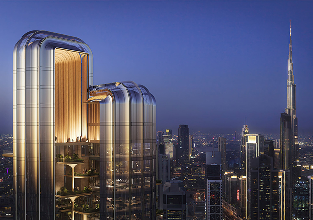
 The Burj Dubai ... heading past the 700 m mark.
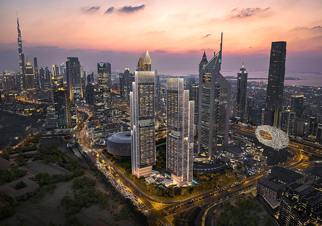
The Burj Dubai tower will be the tallest structure ever built; when completed, it will be more than 700 m tall and have more than 160 floors.
Designed to be the centrepiece of the large-scale Burj Dubai development, the tower has a total floor area of 460,000 sq m that includes residential, hotel, commercial, office, entertainment, shopping, leisure, and parking facilities.
The client of Burj Dubai Tower is Emaar Properties. Turner International is the construction manager, while the Samsung joint venture (which includes Belgium’s Besix and Dubai’s Arabtec) is the general contractor.
The design of tower is derived from geometries of the desert flower which is indigenous to the region, and the geometric patterns embodied in Islamic architecture. The tower massing is organised around a central core with three wings. Each wing consists of four bays. At every seventh floor, one outer bay peels away as the structure spirals into the sky. Unlike many super-highrise buildings with deep floor plates, the Y-shape floor plans of Burj Dubai maximise views and provide tenants with plenty of natural light.
The modular Y-shaped building, with a setback at every seventh floor, was part of the original design concept that allowed Skidmore, Owings and Merrill (SOM) to win the invited design competition.
The tower superstructure of Burj Dubai is designed as an all-reinforced concrete building with high-performance concrete from the foundation level to level 156, and is topped with a structural steel-braced frame from level 156 to the pinnacle.
The tower massing is also driven by wind engineering requirements to reduce dynamic wind excitation. As the tower spirals into the sky, the building’s width and shape diminish, thus reducing wind dynamic effects, movement, and acceleration. Integrating wind engineering principles and requirements into the architectural design of the tower results in a stable dynamic response, taming the powerful wind forces.
Lateral load resisting system
The tower’s lateral load resisting system consists of high-performance, reinforced concrete ductile core walls linked to the exterior reinforced concrete columns through a series of reinforced concrete shear wall panels at the mechanical levels.
The core walls vary in thickness from 1,300 mm to 500 mm and are typically linked through a series of 800 mm to 1,100 mm deep reinforced concrete or composite link beams at every level. Due to the limitation on the link beam depth, ductile composite link beams are provided in certain areas of the core wall system. These composite ductile link beams typically consist of steel shear plates, or structural steel built-up I-shaped beams, with shear studs embedded in the concrete section. The link beam width typically matches the adjacent core wall thickness.
At the top of the central reinforced concrete core wall, a very tall spire tops the building, making it the tallest tower in the world for all categories. The lateral load resisting system of the spire consists of a diagonal structural steel bracing system at level 156.
Floor framing system
The residential and hotel floor framing system of the tower consists of 200 mm to 300 mm two-way reinforced concrete flat plate slabs spanning approximately 9 m between the exterior columns and the interior core wall. The floor framing system at the tips of the tower floor consists of a 225 mm to 250 mm two-way reinforced concrete flat plate system. The floor framing system within the interior core consists of a two-way reinforced concrete flat plate system with beams.
Foundation system
The tower is founded on a 3,700-mm-thick high-performance reinforced concrete pile supported raft foundation at -7.55 DMD. The reinforced concrete raft foundation utilises high-performance self compacting concrete (SCC) and is placed over a minimum 100 mm blinding slab over a waterproofing membrane, over at least 50 mm blinding slab. The raft foundation bottom and all sides are protected with waterproofing membrane.
The high-performance reinforced concrete bored piles are 1,500 mm in diameter, extending approximately 45 m below the base of the raft. All piles utilise SCC with w/c ratio not exceeding 0.30, placed in one continuous concrete pour using the tremie method. The final pile elevations are founded at -55 DMD to achieve the assumed pile capacities of 3,000 tonnes.
A robust cathodic protection system for both the bored piles and the raft foundation system protects the foundation and the reinforced concrete raft against the severe and corrosive environment (chloride and sulphate) of the soil at the Burj Dubai site.
Superstructure construction
The foundation system, including pile and the raft foundations, were completed in February 2005, and superstructure construction for the tower started in April 2005.
The original construction programme is very tight. To complete the project within 48 months, the Samsung Joint Venture (SBAJV) established the following strategic approach:
• Achieve a three-day-cycle for structural works;
• Develop optimum transportation systems with large-capacity high-speed equipment;
• Utilise optimum formwork system to accommodate various building shapes along the building height;
• Develop organised logistic plans throughout the construction period; and
• Apply all high-rise construction technologies available at the time of construction.
Since the construction planning is extensive and cannot be covered in detail in this paper, the major construction planning works can be summarised as follows.
Planning for the concrete work
Prior to the construction of the tower, extensive concrete testing and quality control programmes were put in place to ensure that all concrete works are done in agreement with all parties involved, including the supervision consultant (Hyder), the owner independent testing agency (IVTA), the concrete supplier (Unimix), top quality team CTL, and Samsung Engineering and Construction Task force team. These programmes started from the early development of the concrete mix design until the completion of all test and verification programmes.
The testing regimes included, but were not limited to the following programmes:
• Trial mix designs for all concrete types needed for the project;
• Mechanical properties, including compressive strength, modulus of elasticity, and split tensile strength;
• Durability tests, which included initial surface absorption test and the 30-minute absorption test;
• Creep and shrinkage test programme for all concrete mix design;
• Water penetration tests and rapid chloride permeability test;
• Shrinkage test programme for all concrete mix designs;
• Pump simulation test for all concrete mix design grades up to at least 600 m; and
• Heat of hydration analysis and tests, which include cube analysis and tests, and full-scale heat of hydration mock tests for all the massive concrete elements that have a dimension in excess of 1.0 m. These tests are needed to confirm the construction sequence of these large elements and to develop curing plans that are appropriate for the project, considering major daily and seasonal temperature fluctuations.
Site logistic plan
The Burj Dubai site area is approximately 105,600 sq m – encompassing the tower, the office annex, the pool annex, and the parking areas – and divided into three zones (Zone A, Zone B, and Zone C). The site logistic works and planning works are constantly evolving to reflect current construction activities, lay-down areas, site traffic circulation, etc. Figure 1 provides a snapshot of the site logistic plan after 14 months of construction.
Three-day cycle technologies
The tower, consisting of more than 160 floors, was expected to be completed within a very tight schedule and three-day cycle. Hence, the following key construction technologies were incorporated to achieve the three-day cycle set for the concrete works:
• Auto climbing formwork system (ACS);
• Rebar pre-fabrication;
• High-performance concrete suitable for providing high strength, high durability requirement, high modulus, and pumping;
• Advanced concrete pumping technology;
• Simple drop head formwork system that can be dismantled and assembled quickly with minimum labour requirements;
• Column/wall proceeding method, part of ACS formwork system.
Construction sequence & ACS
Figures 2 and 3 depict the construction sequence of the tower and show the ACS, designed by Doka. The ACS formwork is divided into four sections consisting of the centre core wall that is followed by the wing wall construction along each of the three tower wings. Figure 2 also demonstrates the following construction sequence:
• The centre core wall construction is followed by the centre core slab construction;
• The wing wall construction is followed by the wing flat plat slab construction; and
• The nose columns are followed by flat plate and flat slab construction at the nose area.
In addition, the core walls are tied to the nose columns through a series of multi-storey outrigger walls at each of the mechanical levels.
The construction of these outrigger walls is complex and time-consuming because of the congestion of reinforcing bars at the connection zones. Therefore, the reinforcing bars are now replaced with structural steel sections to help resolve the design forces more effectively at the joints, eliminating the rebar congestion issues, and most importantly ensuring the joint integrity. These levels were constructed at a later stage and taken out of the critical path.
Rebar prefabrication
Most of the reinforcing bars for the core walls, wing walls, and the nose columns were prefabricated at the ground level as shown in Figure 3. This rebar fabrication and pre-assembly method resulted in many quality control advantages and reduced the number of workers going up and down the tower. Moreover, whenever possible, the rebar was assembled in double-storey modules to speed up the vertical element construction time.
Composite link beams
In addition to connecting the vertical core wall elements rigidly for maximum strength and stiffness for the lateral load resisting system, the link beams are also used as means of transferring and equalising the gravity loads between the vertical members (core-wall elements and nose columns). This equalises stresses and strains between the members.
Because the link beams are subject to large shears and bending moments, many of the link beams had to be composite (steel members encased in high-strength concrete). Thus the steel beams imposed special demands on the cranes, pre-assembly and lifting methods.
Slab formwork system
Figure 4 shows a drop head system used for the slab construction. Meva Deck Drop Head slab formwork system was selected because of its installation simplicity, lightness, panel formwork material and strength, prop strength and stiffness, system flexibility and suitability for the slab hanging geometry, and allowance for cambering where needed.
Concrete pumping
The utilisation of high-strength concrete and concrete pumping technologies was critical in the construction of the project. Table 1 provides for a summary of the concrete types used for both the vertical and horizontal members.
Direct concrete pumping and delivery methods required considerations for the following:
• Selecting an optimum concrete mix design with excellent flow characteristics to minimise/avoid blockages;
• Choosing equipment that has enough capacity to deliver concrete to the highest level, more than 160 floors up;
• Designing a pipe line that can be installed with maximum construction efficiency;
• Selecting equipment and pipe line system that work well with the site’s overall logistics and planning; and
• Maintaining quality control of the pumping system and placement method by monitoring all components of the system and ensuring the concrete properties required.
A horizontal pump simulation test was performed, using over 600 m of pipe length to confirm the pump capacity and evaluate the overall pressure losses in the pipes due to friction/connections/concrete type, etc. BSA-14000-SHP-D form Putzmeister was utilised for all concrete grades. See Table 2 for a summary of the horizontal pump simulation system.
Major equipment
Selecting the optimal equipment and vertical transportation system for construction requires ongoing analysis and constant modifications due to the dynamic nature of the project during its construction life. Since the project is more than 160 floors, close coordination of many overlapping activities of various trades, throughout the construction period, required careful planning, analysis, scheduling, and regular coordination.
While the process of selecting equipment for this project was extensive, it can be summarised to include cranes, hoists, and concrete pumping equipment.
Tower cranes
Three high-capacity self-climbing luffing type tower cranes were optimally selected and located at the centre core of the tower as shown in Figure 3.
Tower Main Hoist
Figure 5 depicts the location of the main hoists and the hoist specifications. The hoists were installed in three different phases following the construction sequence of the tower. Additional Jump hoists were installed in accordance with the specifications shown in Figure 5.
Concrete pumping equipment
While the horizontal concrete pump simulation test was very successful and indicative that repumping was not required, pumping the concrete vertically and under different environmental conditions could potentially present unexpected complications. Therefore, a secondary pump was in place at level 124 in case of an emergency situation.
Three major pumps were placed at the ground level. Pumping line 1 situated at the centre core, with pumping lines 2, 3 and 4 at the south, west, and east wings of the core.
An additional pumping line 5 was located at the centre core area for emergency use. Most of the concrete has been pumped directly to the highest concrete elevation, that in excess of 585 m.
Spire, pinnacle assembly & lifting
At Level 156, the reinforced concrete core wall has reached its highest point and serves as the foundation for the spire’s structural steel works. The central pinnacle structure, which consists of 1,200 mm to 2,100 mm diameter structural steel pipe, varies in thickness from 60 mm at the lowest level to 30 mm at the top.
The structural steel works above level 156 consists of the spire structure surrounding the central spine pinnacle structure, and provides the basis for its lateral support and stability.
The spire structural system consists of an exterior diagonal braced frame system to provide for the lateral stability system. While the spire structural steel works is fabricated in Dubai, the pinnacle structure is procured and made in Korea and shipped to Dubai for final fabrication and assembly.
The erection of the spire and the pinnacle starts from level 156, and the erection of the spire is done in the traditional steel construction method. However, the pinnacle pipe sections are stacked from level 156 and lifted to the final position from within the spire as shown in Figure 6.
The lift of the pinnacle will occur in three steps. After each lifting step, the cladding on the pinnacle will be completely installed. The sequence of the pinnacle installation, shown in Figure 7, is as follows:
• Erection of the spire structure;
• Installation of the support beam;
• Installation of the lifting block and assemblies;
• Installation of the lifting equipment and assemblies;
• Lifting the pinnacle in a three-step process;
• Installing cladding after each lift;
• Completing lifting of the pinnacle and all connection connections (gravity and lateral); and
• Completion of the cladding installation
Conclusion
The Burj Dubai project demonstrates that tall building system development is always directly related to the latest developments in material technologies, structural engineering theories, wind engineering, seismic engineering, computer technologies, and construction methods. The project capitalises on advancements in these technologies, the development of supertall buildings and the art of structural engineering.
As of today, the Burj Dubai is the tallest man made structure in the world in all categories, and it has become a catalyst for further development in high-rise construction in the Middle East and throughout the world. The project is another step forward in meeting the technological challenges of future construction.
* Council on Tall Buildings & Urban Habitat (CBTUH) held its eighth World Congress in Dubai last month.
** The paper was prepared by Ahmad Abdelrazaq, executive vice president, High-rise building Team at Samsung Engineering & Construction, Kyung Jun Kim, project director of Burj Dubai project and vice president, Samsung Engineering and Construction and Jae Ho Kim, engineering manager at Burj Dubai project, Samsung Engineering and Construction. Abdelrazaq was involved in the development of the structural and foundation systems of the Burj Dubai project while at SOM, as the senior project structural engineer.


