


 BIG.jpg)
.jpg)


.jpg)


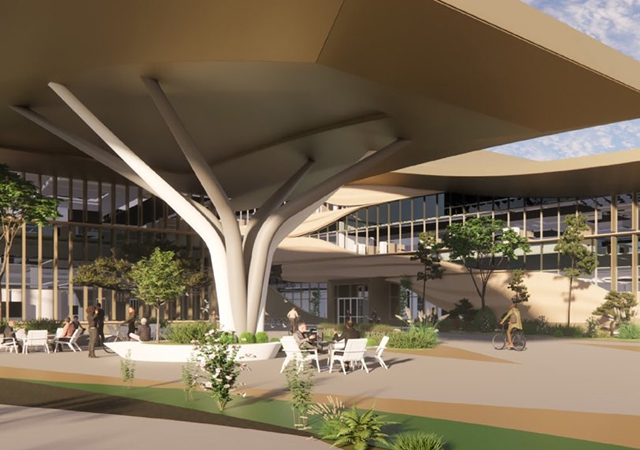
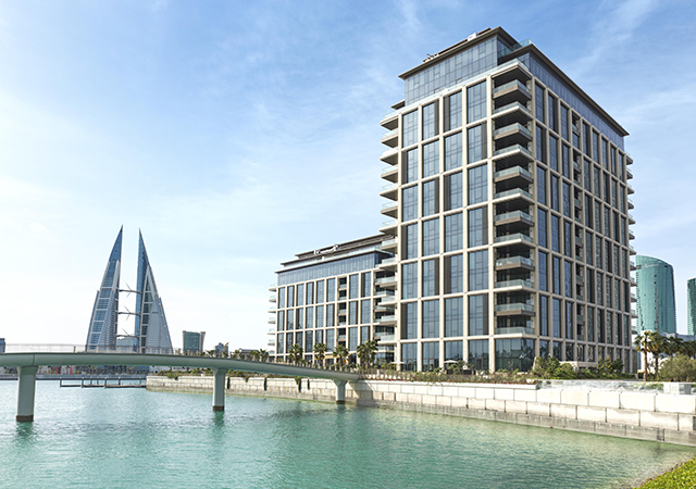
The concept design of the Bahrain World Trade Center towers – which forms the focal point of a masterplan to rejuvenate an existing hotel and shopping mall in central Manama – was inspired by the traditional Arabian wind towers in that the very shape of the buildings harness the unobstructed prevailing onshore breeze from the Gulf, providing a renewable source of energy for the project.
The two 50-storey sail-shaped office towers taper to a height of 240 m and support three 29-m-diameter horizontal-axis wind turbines.
The elliptical plan forms and sail-like profiles act as aerofoils, funnelling the onshore breeze between them as well as creating a negative pressure behind, thus accelerating the wind velocity between the two towers. Vertically, the sculpting of the towers is also a function of airflow dynamics – as they taper upwards, their aerofoil sections reduce. This effect, when combined with the increasing velocity of the onshore breeze at increasing heights, creates a near equal regime of wind velocity on each of the three turbines. Understanding and utilising this phenomenon has been one of the key factors that has allowed the practical integration of wind turbine generators in a commercial building design.
Wind tunnel testing (Figure 1) has confirmed how the shapes and spatial relationship of the towers sculpt the airflow, creating an “S’ flow whereby the centre of the wind stream remains nearly perpendicular to the turbine within a 45-degree wind azimuth, either side of the central axis. This increases the turbines’ potential to generate power while reducing fatigue on the blades to acceptable limits during wind skew across the blades.
The specific architectural forms of the Bahrain World Trade Centre towers were borne from using the nautical expression of a sail to harness the consistent onshore breeze, potentially to generate energy using wind dynamics, as well as to create two elegant towers for Bahrain, which would transcend time and become one of a kind in the world.
Background
Whilst the impetus for this innovative design solution came entirely from Atkins’ chief architect, Shaun Killa, the client readily embraced the concept to portray to the world that Bahrain is committed to options that reduce demand on fossil fuel energy reserves and will move urban and building design in desert climates in a more sustainable direction. The complexity of integrating large-scale wind turbines in a building structure is not to be underestimated and the client expects a key benefit from this project to be the knowledge and experience gleaned which can then be disseminated to design teams globally.
The wind climate in the Arabian Gulf with its dominant sea breeze characteristic is conducive to harnessing wind energy and allows designers to move away from the more conventional omni-directional solutions and consider uni-directional wind turbine options that in many respects, lend themselves to the large-scale integration in buildings.
Research by Atkins has shown that the large-scale integration of turbines into buildings mostly fails because of the excessive cost (up to 30 per cent of the project value) associated with the adaptation of the building design, and also as a result of high research and development costs for special turbines. From the outset, this project had as its primary basis of design the utilisation of conventional technologies and the development of a built form that would be sympathetic to receiving wind turbines. The premium on this project for including the wind turbines was less than three per cent of project value.
So with the benefit of a favourable wind climate and a design philosophy that minimised turbine R&D/building costs, Atkins, with a team of world-leading technologists moved forward with the design and addressed the key issues of:
• Producing technically viable solutions;
• Balancing energy yield/benefit with investment.
 |
Section through bridge |
Design
While, the building is not intended to be a low carbon emission solution by European and other world-wide standards, it does include a number of other design features reduce carbon emissions when compared to other buildings in the Middle East. These are summarised below:
• Buffer spaces between the external environment and air-conditioned spaces – examples include a car park deck above and to the southern side of the mall which will have the effect of reducing solar air temperature and conductive solar gain;
• Deep gravel roofs in some locations that provide kinetic insulation;
• Significant proportion of projectile shading to external glass facades;
• Balconies to the sloping elevations with overhangs to provide shading;
• Where shading is not provided to glazing, a high-quality solar glass is used with low shading co-efficient to minimise solar gains;
• Low leakage, openable windows to allow mixed mode operation in winter months;
• Enhanced thermal insulation for opaque fabric elements;
• Dense concrete core and floor slabs that will level loads and reduce peak demand with associated reductions in air and chilled water transport systems;
• Variable volume chilled water pumping that will operate with significantly less pump power at part loads than conventional constant volume pumping;
• Low pressure loss distribution for primary air and water transport systems that reduces fan and pump power requirements;
• Total heat energy recovery heat wheels of fresh air intake and exhausts to recover “coolth” from the vitiated air and recover it to the fresh make up air;
• Energy-efficient, high-efficacy, high-frequency fluorescent lighting with zonal control;
• Dual drainage systems that segregate foul and waste water and allow grey water recycling to be added at a later date;
• Connection to the district cooling system that will allow an order of magnitude improvement on carbon emissions;
• Dual flush WC and electronic taps with excess water flow restrictors;
• Reflection pools at building entrances to provide local evaporative cooling;
• Extensive landscaping to reduce site albedo, generate carbon dioxide (C02) and provide shading to on-grade car parks;
• Solar-powered road and amenity lighting.
Integrated wind turbines
Wind analysis: The horizontal-axis wind turbines are normally pole-mounted and turn to face the direction of the wind, thus maximising energy yield. However, the practical application of such turbines to buildings in variable direction wind climates is very difficult. The majority of architectural studies deploying building-integrated, horizontal axis turbines deploy the principle of a fixed turbine as in the case of the Bahrain World Trade Centre. In addition, at the time of design development for this project, large scale proven vertical axis turbines were not available for building applications.
The fixed horizontal turbine suffers the drawback of only being able to operate with wind from a limited azimuth range, if problems with blade deflections and stressing through excessive skew flow are to be avoided. From the outset of this project, the shape of the towers has been designed to capture the incoming wind and funnel it between the towers.
Extensive wind tunnel modelling, later validated by COD modelling (Figure 1) have shown that the incoming wind is in effect deflected by the towers in the form of an S-shaped streamline which passes through the space between the towers at an angle within the wind skew tolerance of the wind turbine. Engineering predictions show that the turbine will be able to operate for wind directions between 270 and 360 degrees, however, caution has been applied and turbine predictions and initial operating regimes are based a more limited range of between 285 and 345 degrees. At all wind directions outside of this range, the turbine will automatically adopt a “standstill” mode. It is no coincidence that the buildings are orientated to the extremely dominant prevailing wind.
The funneling of the towers has the effect of amplifying the wind speed at the turbine location by up to 30 per cent. This amplification, in conjunction with the shape of the towers (larger effect at ground) and the velocity profile of the wind (lowest at ground) has the effect of balancing the energy yield to the extent that the upper and lower turbines will produce 109 and 93 per cent when compared to 100 per cent for the middle turbine.
Components & control: The fixed, horizontal axis wind turbines comprise the following key components:
• Nacelle: including enclosure with gearbox, generator, cooling system and associated control systems;
• Rotor;
• Bridge;
• Control, monitoring and safety systems; and
• Electrical building interface.
The outline specification details for each wind turbine are detailed in Table 1.
The nacelles – the cowling containing the gearbox, brake, controls, etc. – have been designed to sit on top of the bridge, rather than within it, to portray the functionality of the turbine, which is of the simple and robust “stall controlled” type. The stall control is a passive way of limiting power from the turbine. The rotor blades are bolted onto the hub at a fixed angle and the profile has been designed to ensure that the moment the wind speed becomes too high, it creates turbulence on the leeward side of the rotor blade and prevents lift, stalling the blade so that the power output stabilises at a maximum output.
The full power of about 225 kW will be achieved at 15 to 20 m/s (Figure 2) depending on air density. In the event of extremely high wind speeds under operating or standstill modes, the tip of the blade extends by centrifugal force and rotates to act as a self-regulating governor brake, through the exertion of a drag force.
For this project, the nacelles have a conventional design with some enhancements to suit the desert application and to increase the structural safety. The guidelines in the Danish code of practice1,2 have been used for increasing the structural safety to “High Safety class”. Conventionally, Eurocodes would be referenced, but they do not address high safety classifications.
Each nacelle operates independently and is not affected by the failure of another.
Bridges: A key part of the design is the determination of loads on the rotor, through the nacelle and thence onto the bridge and buildings, so that structures can be analysed for strength and fatigue.
The load calculation approach for this project has been made by the bridge design consultant in conjunction with the wind turbine manufacturer using a version of the industry-best wind turbine simulation tool, “Flex4”3, specially adapted to take account of the influences of the buildings and the bridges. A total of a 199 different load cases has been modelled for each turbine and validating calculations or operational processes prepared to theoretically demonstrate that the turbine and bridge would survive without excessive fatigue. During the early stages of operation, this theoretical analysis will be validated and appropriate adjustments made to the operating regime that may increase or decrease energy yield.
The bridges are ovoid in section (Figure 3) for aerodynamic purposes and are relatively complex structures because they incorporate maintenance-free bearings where they connect to the buildings to allow the towers to move 0.5 m relative to each other. In addition, the bridges that span 31.7 m and support a nacelle with a mass of 11 tonnes have been designed to withstand and absorb wind-induced vibration and vibrations induced by both an operating and “standstill” turbine.
Analysis by the bridge designer has been undertaken to estimate the natural frequency of the bridge and to ensure it does not conflict with the frequency of exciting vibrations of itself or the building. Further precautions are included in the design to allow the bridge to be damped, if in practice vibrations are found to be problematic during commissioning. These include the facility to add spoilers to the bridge and to adjust the tuned mass damper.
The bridge is a shallow V-shape in plan (173 degrees) to take account of blade deflection during extreme operating conditions and to afford adequate clearance and thus avoid blade strike. Under these conditions, blade clearance to the bridge of 1.12 m is achieved. The worst scenario is with blade tips extended giving a factor of 1.35 safety margin – for which adequate clearance is still achieved. Additionally, a laser blade position monitoring system is incorporated that will set the turbine to standstill if deflections become excessive.
Turbine control, monitoring and safety is delivered through three systems:
• Wind turbine control system (WTCS) that directly controls and monitors the turbines;
• Extended wind turbine monitoring system (EWTMS) that is a separate monitoring system developed for this project;
• Building monitoring system (BMS).
The WTCS, an industrial quality control system specifically evolved to control and monitor wind turbines, is robust and reliable, In addition to its control and monitoring functions, it is able to shutdown turbines safely in the event of adverse climatic conditions or due to other factors that will threaten life-safety or turbine life. It is an on-line system that allows operators anywhere to gain access to the operating data and grant those with appropriate authorisation control of the turbines.
It has an in-built independent, emergency, safety surveillance system that will monitor possible faults in the turbine and the immediate turbine operating environment and bring it to a standstill, if required. This system overrides the electronic control system. The WTCS obtains data relating to the turbine operating environment via the BMS which is summarised in Table 2. Finally the WTCS retains significant data regarding turbine operation and provides tools for analysis. For this specific application where safety is crucial the WTCS fully integrates the special control and monitoring functions given in Table 3.
The EWTMS is a project bespoke system that works in conjunction with WTCS to provide monitoring and calibration of the control system operational limits required for this specific application (Table 4). In total the EWTMS has 43 additional sensors.
In the event of a control system failure, the turbine is brought to standstill by the tip brake working in conjunction with the hydraulic brake through a power fail – fail-safe mechanism.
The BMS will be used as a means of providing connectivity from remote sensors to WTCS and EWTMS.
Electrical building interface: Each nacelle has a 225 kW nominally rated, 400V, closed, four-pole induction, 50 Hz, asynchronous generator that is connected to a generator control panel inside each tower. From each generator’s control panel, separate low-voltage (LV) feeders connect to the interfaces on the main LV switchboard at three substations. These substations supply electricity to the landlord areas of the development.
The generators are designed to start and run in an asynchronous mode and in parallel with the electricity authority’s grid, but at this stage it is not possible to export electricity to the electricity supply authority in the event of a surplus being available.
In the event of an outage or reduction in voltage/frequency from the board’s power supply the turbines will be shut down.
The length of the LV feeders from the generator control panels to the building electrical system interface points, required a careful study in order to avoid an excessive voltage drop and to ensure there were no problems with harmonics and voltage disturbances. Extensive dynamic simulation studies were carried out by the turbine manufacturers’ electrical specialist partner company to ensure compliance with relevant IEC standards.
Design validation
The design has been validated using a SARM (safety, availability, reliability and maintainability) analysis by Ramboll with Atkins-Science and Technology in a review role. Table 5 shows the issues that were addressed.
Energy yield
The projected energy yield from the turbines taking into account wind and availability data is summarised in Table 6. This amounts to between 1,100 and 1,300 MWh per year and will amount to approximately 11 to 15 per cent of the office tower’s electrical energy consumption. In carbon emission terms this equates conservatively to an average of 2,900 kgC (oil burning power station) or 2,000 kgC (gas burning power station). Since this is a world first and because wind turbines have not been placed 160 m above ground level and between buildings, the yield may even be higher.
Final lesson
It should be appreciated that this was a fast-track design and construction programme and that the integration of large-scale wind turbines into a building has involved extensive research and development by probably some of the most capable specialists available. The initial phases of operation of this project will be the final part of the learning curve, during which significant monitoring and fine tuning are required in order that full potential of this innovative application may be properly realised and understood.
References:
1) Danish code DS409. “Code of Practice for the Safety of Structures”
2) Danish code DS412. “Code of Practice for the structural use of steel”
3) Flex4 : Simulation of wind turbine dynamics. Load analysis software used by Ramboll/Norwin and originally developed by the Technical University of Denmark
Acknowledgements:
Building design (all technical disciplines) was by Atkins – Middle East. The wind turbine and bridge design and manufacturing specialists involved are Ramboll Denmark – consultants, Norwin – turbine manufacturer, Elsam Engineering – power generation. Wind Tunnel Testing was done by BMT and Atkins, DE2 and Atkins, Science & Technology have executed high level technical reviews.


