


.jpg)


.jpg)


.jpg)


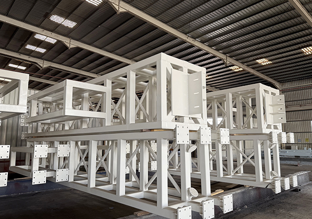
 At the start ... tubular pile clutches are welded at the factory in China,
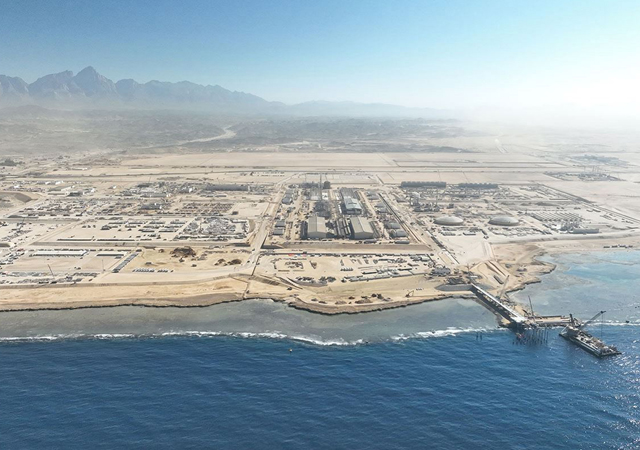
ESC Al Sharafi Steel of Abu Dhabi recently completed the Oil Terminal Two (OT2) project for Port of Fujairah, a project that was awarded in February last year.
The company’s scope of work included design, manufacture and supply of more than 12,000 tonnes of combi-wall steel sheet piles. It was also responsible for commissioning and operating its blasting and painting works on site at Fujairah to provide full corrosion protection for the project.
“ESC also executed the installation and extension works for this important infrastructure expansion,” says Darryll Sinnappa, area manager for ESC Al Sharafi Steel.
Athena, the contractor, and ESC proposed the ESC combi-wall tubular pile system, which eventually won the award from the Port of Fujairah and its engineer, MUC of the Netherlands. During the design stage of the project, ESC held site meetings in the UAE and visited MUC’s geotechnical and structural team in Terheijden, Netherlands. ESC ensured that all aspects required by the client and its engineer were achievable.
ESC not only worked with the owners but visited the site and also liaised with Athena, both during the design and implementation of the project. Designs of the wall system took into account the preferred method of construction detailed by Athena and were adapted accordingly whilst ensuring that the stringent safety stipulations of the clients’ engineers were followed in terms of seismic and structural conditions.
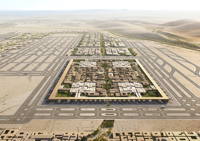
The Port of Fujairah proposed to construct a new quay wall for an oil terminal facility to be constructed to the north of the existing port facility. It will serve as a vessel loading facility for oil products.
The type of retaining wall used is a steel tubular pile wall with sheet pile infills, restrained by tie-rods to buried sheet pile anchor wall. This wall was backfilled with locally-dredged material.
The design of the sheet pile wall was undertaken by ESC Al Sharafi Steel and detailed in a series of reports. The scope of the design covered by these reports included:
• Evaluation of geological data and existing site conditions to determine a range of geotechnical parameters for use in the designs;
• Analysis of the retaining wall and restraint system, given the geotechnical parameters, site requirements and loading considerations, including seismic design;
• Specification and design of necessary sheet pile and tie-rod components to withstand the calculated geotechnical and imposed loads;
• Evaluation of the corrosion conditions and design of the sheet pile system components to accommodate these conditions, including specification of protective coatings; and
• Various method statements required for specific tasks, including painting, bitumen sealing and clutch strength testing.
The design scope was broken into a series of design submissions, which addressed each of the key design issues. The scope of the design within these reports did not extend to the following issues:
• Overall layout of the port, including hydrodynamics or other overall design considerations involved with developments of this nature;
• Environmental impact considerations, excepting specific products that may be specified in the design and have to comply with environmental requirements;
• Design of capping beams, fenders, quick-release hooks, mooring rings, ladders or other fixtures on the sheet pile structure. The loads from these respective items will be considered in the design;
• Design of buildings, cranes, pontoons, dolphins or other structures associated with the project; and
• Cathodic protection and scour protection.
Project criteria
The tender provides for a design life of 50 years for the works, specific loading and seismic requirements, load case specifications, structural dimensions and tidal information. British Standards were generally used as the basis for the design and included BS5950 structural use of steelwork in building; BS6349 marine structures; BS8002 earth retaining structures; BS8081 ground anchorages; BS EN 10219 cold-formed welded structural hollow sections of non-alloy and fine grain steel; BS EN 10249 cold-formed sheet piling of non-alloy steels; and BS EN 12063 execution of special geotechnical work – sheet pile walls.
Other publications that were referred to included PIANC’s (The World Association for Waterborne Transport Infrastructure) seismic design guidelines for port structures, and the Global Seismic Hazard Assessment Programme’s 1999 global seismic hazard map.
Computer-based calculations were performed using software compatible with the Microsoft Windows operating system. Reports were submitted in PDF format. Drawings were produced in Autocad. The following specific design software was employed to assist with the design:
• Plaxis 2D – V8 Professional: a finite element package intended for 2D analysis of deformation, stability and groundwater flow in geotechnical engineering. Using the Plaxis package, earth and retaining wall structures were constructed stage by stage, similar to the actual construction method. This allowed the modelling of stage loads and time dependant and cumulative effects. The package offered various soil models to simulate a variety of soil conditions, as well as time dependant control over groundwater and pore pressures. Local and overall stability, deformations and loads on all structures were readily obtainable. The addition of the dynamics package allowed the modelling of the soil structures response to harmonic inputs, such as driving forces, wave actions and earthquakes. The great advantage of the Plaxis analysis was that it allowed the entire structure to be modelled simultaneously so the interactions between different components could be analysed and resultant net effects viewed at any point within the model.
• Static Probing: CPT (core penetration test) data was analysed using Static Probing by Geostru. The software provided graphical plots of the CPT readings, stratigraphic interpretations and tabulated soil parameters at each test location;
• Strand 7, a general-purpose 3D finite element package, with both linear and non-linear capabilities. Designed by Strand7, Australia, the software allowed the accurate modelling of intricate and detailed components, with complex load applications. The Strand software was primarily used for simulation of the steel structure elements and connections.
Discussion of submissions
• Evaluation of geological data: The report aimed to evaluate the data from the soil investigations and laboratory tests and from this, determine accurate soil profiles across the project site, including the assignment of soil parameters. Two soil investigation reports provided the data. One set dated back to 2006 and formed the basis for the tender designs.
The second set of data was provided by a soil investigation that was carried out after the commencement of the works. This soil investigation consisted of 13 boreholes and eight CPTs specifically targeted at the zones where the works were to be carried out. The results from these boreholes were the primary source of geological information, however the older set of logs were still maintained and used as a reference. The results of the soil tests allowed the assignment of soil parameters to the various soil types and strata. These parameters were measured values, and were referred to as representative soil parameters.
• Seismic evaluation and considerations: Seismic design was in accordance with the Pianc’s seismic design guidelines for port structures. Design acceleration was in accordance with UBC1997, volume 2, category 2. In addition, ESC provided a seismotectonic assessment of the regional hazard.
• Retaining wall design calculations: The local stability calculations of the retaining wall were performed in accordance with the requirements of BS8002. The analysis was performed for a variety of load cases, considering stage-by-stage construction and the resulting cumulative effects. The results obtained from the analysis of local stability were considered design values with no further addition of load factors or extension of the embedment. No moment reduction was applied to the walls due to relative soil/wall stiffness considerations (for example, Rowe reductions). Overall stability of the main wall, tieback and anchor wall structure was determined using representative soil parameters. A reduction analysis was then performed using the Plaxis software to determine the overall geotechnical factor of safety. For static load cases, the target factor of safety on overall stability was 1.4.
• Main wall and anchor wall component capacities: The design of the sheet pile system was performed in accordance with the requirements of BS5950-1. In determining the required structural capacity, the full yield strength of the material was utilised. The capacity of the main wall components was then compared with the loads determined in retaining wall design calculations reports, and a structural factor of 1.2 for static conditions and 1.1 for seismic conditions maintained.
• Tie-rod component capacities: Tie-rod design was performed in accordance with BS8081. Geotechnical loads were calculated from representative soil parameters and considered working load values. The effects of the various load cases were considered. Tie-rod capacity was designed to have a factor of safety of 2.0 (uncorroded) and 1.75 (corroded) on static load conditions, and a factor of 1.1 applied in seismic conditions. Separate additional tie-rods provided for quick release hooks. No bollard loads were considered in the main tieback system. Corrosion of the tie-rod system was considered for 35 years.
• Waling beam component capacity: The design of the sheet pile system was performed in accordance with the requirements of BS5950-1. Corrosion was considered for a period of 35 years. The capacity of the waling beam was designed to maintain a factor of safety of 1.2 in static conditions and 1.1 in seismic conditions.
Coating requirements
The specified coating for the sheet piles required shot blasting to SA2.5 followed by two layers of 250-micron Jotamastic 87. The coating was applied to the top 22.3 m of the front of the ESC tubular piles and the back 4 m. Paint was applied to the full length of the 22-m-long ESC sheet piles. The ESC anchor piles were not coated.
Conclusion
The project has been a great success for ESC, demonstrating its full range of technical and engineering skill being matched with its manufacturing capabilities.


