


.jpg)


.jpg)


.jpg)


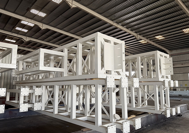
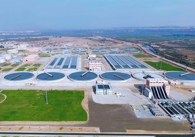
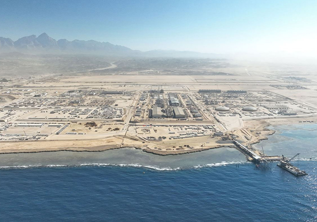
ESC Al Sharafi Steel recently completed a marina wall at a luxury residential complex in the Middle East and the project’s success highlights the company’s expertise in the art of design works.
The proposed structure was an 800-m-longmarina wall, to be used for the mooring of light vessels and recreational craft. It was proposed to construct the quay wall using a permanent sheet pile wall, supported by a tie-back system.
The existing ground site required no additional filling. The finished dredge level was 8.0 m below current existing ground level. Having no further information available, ESC started its work.
The original design called for two retaining methods: caissons and sheet piles. The caissons were to be employed in the breakwater and part of the berthing area. ESC proposed an alternative – to use sheet piles for the entire structure.
Three critical components comprise the proposed retaining structure, namely, the sheet pile wall, tie rods, and anchor wall.
The sheet pile wall would comprise hot-rolled U-type sheet piles. The tops of the sheet piles is to be located 1 m below the finished platform level. The main sheet pile wall is to be anchored by tie rods to an embedded anchor wall. The top of the sheet pile is to be capped by a cast in-situ concrete capping beam, which will maintain wall alignment, distribute anchorage forces and provide a seating for the precast concrete ‘curtain’ panels which are to be suspended in front of the sheet pile wall.
A soil investigation report was conducted and issued.
Conditions were not expected to vary along the length of the quay wall so a single section was used as the basis for the modelling.
The intended life span for the structure was for 50 years. Protection from the effects of corrosion was provided by a sacrificial loss from the sheet piles, and wrappings on the tie rods. No protective coating was to be applied to the sheet pile wall.
Sacrificial loss was considered to occur at the rates as per Table 4-2 of EN 1993-5:2007 for a period of 50 years. The proposed sheet pile was the NSP-IVw. The effects of corrosion loss on this section were also illustrated.
Tie rods were to be wrapped in suitable tape and the threads sealed with mastic. The durability of the wrapping system was taken as 15 years, after which the rods are considered to corrode at a rate of 0.05 mm per year as per BS8002.
All components were designed to provide the required factors of safety in their post corroded state. Modelling was performed using an effective stress analysis based on BS8002, using the Reward analysis software.
The local stability calculations of the retaining wall was performed in accordance with the requirements of BS8002.
An analysis was performed for a variety of load cases, considering stage-by-stage construction and the resulting cumulative effects.
The results obtained from the analysis of local stability using the above considerations were considered design values with no further addition of load factors or extension of the embedment. No moment reduction was applied to the walls due to relative soil/wall stiffness considerations (such as Rowe reductions).
The overall stability of the main wall, tie-back and anchor wall structure was to be determined using representative soil
parameters.
For static load cases, the target factor of safety on overall stability was 1.4.
The load applied to each model was:
Surcharge loads:
• Static analysis:10 kPa;
• Seismic analysis: N/A; and
• Live loads:N/A.
Hydrostatic loads:
• Tidal drawdown: 0.9 m.
Soil parameters were followed as per the boreholes provided from the soil investigation report shown in Table 1. Sheet pile parameters are detailed in Table 2 and tie rod parameters in Table 3.
Acceptance criteria for the performance of the structure followed the recommendations of the following standards:
• BS8002 – Earth Retaining Structures (for retaining walls);
• BS8081 – Ground Anchorages (for anchor loads);
• BS6031 – Code of Practice for Earthworks (for overall stability ); and
• PIANC – Seismic Design Guidelines for Port Structures (for seismic performance).
The following limits were adopted:
Static conditions
Overall considerations:
• Maximum deflection: 0.5 per cent of wall height (serviceability); and
• Minimum factor of safety – Stability:1.4 (serviceability).
Main sheet pile wall and deadman sheet pile wall:
• Bending moment factor of safety:1.2 (design soil).
Anchorage system:
• Tie rod factor of safety (uncorroded): 2.0 (serviceability);
• Tie rod factor of safety (corroded): 1.75 (serviceability); and
• Waling beam factor of safety (uncorroded): 1.2 (design soil).
The results of the static loading are shown in Table 4. The main sheet pile wall and tie rod results have been compared with the capacities for both standard corrosion cases.
The corroded capacities of the components exceed the calculated design loads and conform to the stipulated acceptance criteria. The structure was therefore considered stable under the given design conditions.
This is a classic example of how a marina wall using sheet piles is designed and used as a basis for building.
It proved to be the best solution and most competitive option with the fastest completion timelines possible.


